Ethernet cable wiring is a fundamental technology that connects devices within a network, enabling data transmission and communication. Whether in Dubai, UAE, or anywhere else, Ethernet cables utilize standardized wiring schemes like T568A and T568B to establish reliable connections, ensuring seamless data exchange between computers, routers, and other network components. Understanding Ethernet cable wiring is essential for maintaining efficient and secure networking infrastructure in today’s interconnected world.
I. Ethernet Cable Wiring CAT 6
- Cable Basics: Cat 6 Ethernet Cable Wiring is designed for high-speed data transmission, supporting speeds of up to 10 Gbps.
- Wire Pairs: Cat 6 cables consist of four twisted pairs of wires, often color-coded as blue, orange, green, and brown.
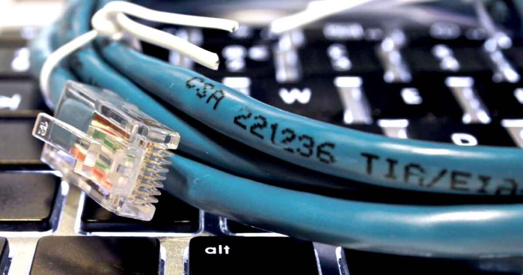
- TIA/EIA Standards: Cat 6 wiring must adhere to TIA/EIA-568-B standards for proper performance.
- Pin Configuration: The standard pinout for Cat 6 cables is T568A or T568B, where wires are arranged in a specific order.
- Avoid Crosstalk: Proper twisting and shielding of pairs minimize crosstalk and interference.
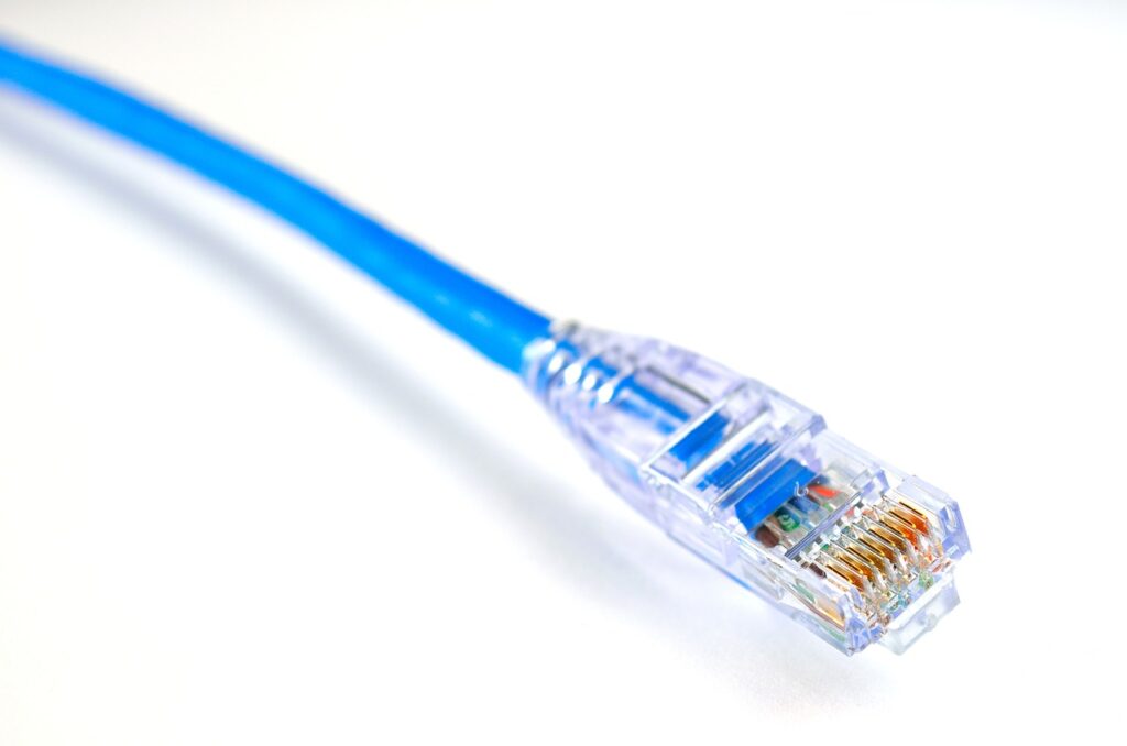
- Termination: Use RJ45 connectors for termination, following the chosen T568A or T568B wiring scheme.
- Testing: To make sure your Cat 6 cable satisfies performance requirements, test it often.
- Length Considerations: Keep cable lengths within recommended limits (usually 55 meters for 10 Gbps).
- Gigabit Ethernet Ready: Cat 6 cables are backward compatible with lower Ethernet standards like Cat 5e and are ideal for Gigabit Ethernet networks.
- Future-Proofing: Installing Cat 6 cabling can help future-proof your network for higher data demands.
II. Ethernet Cable Wiring A Or B
1. Purpose: Ethernet standards A and B are wiring schemes used to connect network devices.
2. Pin Configuration:
A: Pins 1&2, 3&6, 4&5, 7&8
B: Pins 1&2, 3&6, 4&5, 7&8 (flipped pairs)
3. Common Use:
A: Mostly used in commercial installations.
B: More prevalent in home networks.
4. Compatibility:
A and B connectors can work together with a crossover cable.
5. Color Coding:
A: uses white/green, green, white/orange, blue, white/blue, orange, white/brown, and brown.
B: uses white/orange, orange, white/green, blue, white/blue, green, white/brown, and brown.
These differences help prevent wiring errors in Ethernet connections.
A. How Ethernet Cables Are Made?
Ethernet cables are made by twisting four pairs of insulated copper wires together and then wrapping them in a protective outer jacket. The four pairs of wires are twisted to reduce crosstalk, which is interference between the different pairs of wires. The outer jacket protects the wires from damage and environmental factors.
B. How to Connect the LAN Cable to RJ45?
- Strip the outer jacket of the LAN cable about 1/2 inch from the end.
- The four wire pairs inside the cable should be untwisted.
- Trim the wires so that they are all the same length and about 1/4 inch long.
- Make sure that each wire is fully inserted as you insert the wires into the RJ45 connector.
- Insert the wires into the RJ45 connector, making sure that each wire is pushed all the way in.
- A crimping tool is used to crimp the RJ45 connector.
- Check the cable’s functionality by testing it.
C. What Are The 8 Wires in The Ethernet Cable?
The most frequent kind of cable used for wired networks is Ethernet cable wiring. They have 8 wires inside, which are paired in sets of two and twisted around each other. This helps to reduce crosstalk and interference.
The 8 wires in an Ethernet cable:
- Pin 1 – White/Orange: This wire is used for transmitting data from one device to another.
- Pin 2 – Orange: The orange cable on pin two is used to receive data from other devices.
- Pin 3 – White/Green: Data is transferred between devices via this wire.
- Pin 4 – Blue: This wire is utilized to transfer data from one device to another.
- Pin 5 – White/Blue: Data is transmitted from one device to another using this wire.
- Pin 6 – Green: This wire serves to transfer data from one device to another.
- Pin 7 – White/Brown: This wire is used for grounding the cable.
- Pin 8 – Brown: This wire is used for powering the cable.
Note: Not all Ethernet cables use all 8 wires. For instance, while Gigabit Ethernet requires eight wires, 10BaseT and 100BaseTX only require four.